“Sacred geometry” is the art and science of using geometric figures to design sacred architecture or artworks. Recognising that mathematics is something that humans discover – we don’t invent it – and that it corresponds to forms found in nature, to aspects of music, and to cosmological measurements, ancient peoples beginning (as far as we know) with the Egyptians developed the use of geometric forms to lay out their temples and altars. The Greeks further developed geometry in both its sacred and pragmatic aspects. Pythagoras, known for his theorem of the right-angled triangle, was the leader of a mystical religious movement. Though he may (or for all we know, may not) have developed the formal theorem of the right-angled triangle, he was not the first to note its special properties, a triangle with sides of three, four and five units having long been used in Egyptian art.
In the Middle Ages and Renaissance, sacred geometry was used to lay out cathedrals, at all levels of detail from the floor plan to the fine decoration and the composition of the paintings. The sense of harmony and proportion one experiences in a medieval cathedral (or a Greek temple) is not only because of the religious associations of the location, but because geometric principles have been used to lay it out. In contrast, modern architecture is often designed based on a simple grid, and as such does not have the same aesthetic appeal. Although the underlying geometry on which the layout is based is not evident without careful analysis, as humans we seem to respond to the proportions of a geometrically planned building or artwork with pleasure, as we do to a natural scene.
Nature is also full of geometry, from the hexagonal cell of a honeycomb to the spiral of a nautilus shell, and there are excellent reasons of resource optimisation and stability for adopting these structures.
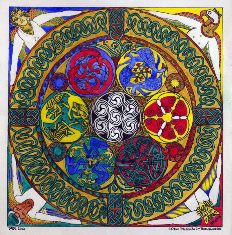
I am interested in creating artworks based on sacred geometry, and indeed on creating religious artworks which refer to the medieval tradition. I became interested initially when I took a class on Celtic design, in which a complex tradition of sacred geometry is embedded, seen both in the pagan works of the La Teine and Hallstadt cultures and in the magnificent illuminated manuscripts of early medieval monks. I have, however, some resources which those early artists lacked, in the form of digital drawing tools, and this guide specifically focusses on the use of such tools in sacred geometry.
Digital Tools
For budgetary reasons I don’t own a copy of Adobe Illustrator, which is probably the premium software for this kind of work (it costs about $500 US). I do have an old copy of CorelDraw version 7, and have recently downloaded a copy of Inkscape, a free software vector graphics program. “Vector graphics programs” are what these various tools are called, meaning, broadly, programs with which you can draw pictures based on lines with a mathematical description, rather than on tiny coloured squares which are described individually (known as bitmap graphics).
One implication of this is that you can scale the pictures up or down without losing detail. Another, of course, is that they, too, are using geometry underneath, and so are entirely suitable for the task at hand.
The traditional tools of the sacred geometer are the compass (for drawing circles) and the straightedge (for drawing lines). From these two elements – circles and lines – they could draw everything they wanted, except of course illustrations of things in the real world, which they drew freehand within the spaces defined by the circles and lines. In theory, then, the only tools we need to use in our digital drawing programs are the circle tool (or ellipse tool constrained to a circle) and the line tool. If you are a purist you can stick to those. Personally I take a few shortcuts, as below.
I also have a copy of the free geometry program KSEG. KSEG is specifically designed for “compass and straightedge” geometry, and is quick to use, but quite basic (and a little quirky until you get used to it). The examples in this article are done in KSEG. I’m not sure that I’d use it for art, though, probably just to play around with the constructions. Apart from anything else it puts visible points everywhere, which is useful for explaining constructions but not for artwork, where they would need to be removed.
I won’t be giving elaborate screenshot-laden tutorials about using the specific programs, since I don’t have Illustrator and my version of CorelDraw is old. Anything you need to know how to do you should be able to look up in the Help, and generally the programs work much the same as each other at the basic level. You select which tool you are currently using by clicking it in a toolbar; it then changes the mouse cursor and also the behaviour you see when you click, drag, double-click, etc.
The selection tool (an arrow) selects individual items on the screen which you can then manipulate in other ways, moving them, changing their properties (like colour or line thickness) and so forth. You will need to right-click or use the menus to get to some of these options.
The ellipse tool draws ellipses when you click and drag. You can (and should) “constrain” the ellipse to be a circle by holding down a key (Ctrl in CorelDraw and Inkscape, Shift in Illustrator apparently), and also make it expand out from the point you first clicked (by holding down Shift in CorelDraw or Inkscape, Ctrl in Illustrator as you drag the mouse). This is the behaviour you will usually want from your circles, and it is equivalent to placing one leg of your compass at that point (click) and positioning the other leg (drag). With a compass you would then have to rotate it to draw the circle; the digital tool does this for you automatically.
In Inkscape, you will need to set fill to “No paint” and stroke to “flat colour” in the Properties dialog (Object > Fill and stroke on the menu). Otherwise you will get filled-in circles instead of the outlines you want.
The freehand drawing tool (pencil/pen) will draw a line between two points that you click, and is the equivalent of the straightedge.
The other main tools I use are the symmetry tools, particularly rotation, since I often base my pieces on a circular shape and want to have smaller elements distributed evenly around the circle. As well as rotating you can also reflect or flip elements (horizontally or vertically). In CorelDraw at least, you have the option to apply the transformation to a duplicate (or copy) of the object, and this can be very useful because it leaves the original in place and moves the duplicate.
I use rotation with duplication as a shortcut when creating regular polygons such as squares or equilateral triangles. Draw the first line where it belongs, duplicate and rotate a number of degrees equal to 360 divided by the number of sides (e.g. 120° for a triangle), and repeat until you have the number of sides you require. Then move them (keeping the same angles) until their ends touch. This is a foolproof way of constructing regular figures and is a lot faster than doing it the purist way with lines and circles. There is a purist way to do this for any given figure of a reasonable number of sides, but some of them are quite arcane (a seven-sided figure is particularly difficult, and the result is imperfect).
Also very useful are guidelines. You can drag these from the horizontal and vertical ruler bars (which I mostly ignore otherwise, since my constructions are based on geometry, not measurement). They look like dotted blue lines, and help you to line things up with each other and save you cluttering your layout with drawn lines which you will later have to remove. You can have angled or sloping guidelines as well as horizontal and vertical ones, except in Inkscape (as far as I can see), in which you will have to use drawn lines. (You can lock these to prevent them from being accidentally moved – right-click and select Object properties, then turn the Lock checkbox on. However, I can’t figure out how to unlock them if you need to – perhaps you can’t.) I believe later versions of CorelDraw (and probably Illustrator) may allow circular guidelines as well, and I am planning to propose to the Inkscape developers that they implement both angled and circular guidelines.
You should turn “snap to guidelines” on in your program if it has this option so that when you click near a guideline the mouse cursor will automatically move slightly to be over the guideline – this makes for greater accuracy.
It is a good idea to use multiple layers in your drawing, one to hold the construction lines (which won’t appear in the final piece) and one to hold the “manifest” lines, which will appear. You can copy or move things from one layer to another and hide the construction line layer to check your progress. You may have to delete the construction lines before exporting the picture to another format, because even if you hide them they will appear when exported in some versions of some programs.
Sometimes you will only want part of a shape, and you will need to erase the rest of it using the eraser tool. In CorelDraw (at least the version I have), if the object is a circle you need to convert it to curves first (Ctrl + Q), and then go into its properties (right-click) and untick the checkbox which says to close the curve, otherwise the erasing won’t work.
You can also use commands to remove areas where two objects overlap (Trim in CorelDraw), to join them together (Weld), or to create another object from the overlapping portion (Intersection). Some programs (such as Illustrator and Inkscape) also enable you to break lines apart at the point where they overlap, after which you can delete one part of the line. See Inkscape’s Path menu and its Help.
That’s about it as far as using the tools goes. The rest of this guide covers the basics of using lines and circles to draw more complicated shapes.
The Mandorla
The mandorla (meaning “almond”; it’s also known as a “vesica piscis”, or fish’s liver) is the almond or fish-liver shape you get when you overlap two equal-sized circles in such a way that the centre of each is on the other’s circumference:
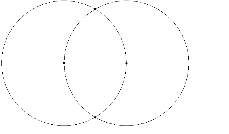
The mandorla was much used in medieval art, often containing Christ enthroned or the Virgin and Child. The symbolism is multiple. The shape is like a stylised fish, Greek “IChThUS” (ΙΧΘΥΣ), which from early times was used as an acronym for “Iesous Christos Theou Uios Soter” – Jesus Christ, God’s Son, Saviour. It also represents the meeting of two worlds (heaven and earth) in the person of Christ. The shape also resembles that of an eye, and it is used as such in art, though mainly in Muslim rather than Christian contexts from the examples I have seen. Finally, it can be seen as lips (by which God utters the Word) or as female genitals (by which Christ enters the world).
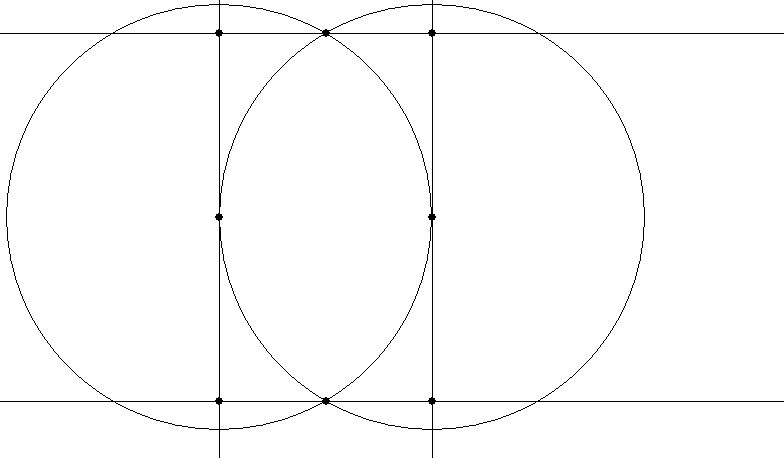
The relationship of the width of the mandorla to its height is the proportion 1:√3, a ratio which turns up in a number of other places in sacred geometry.
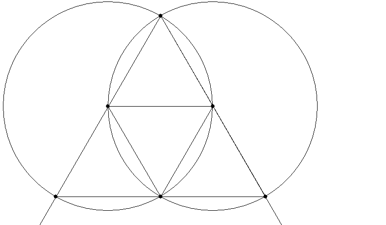
A mandorla can be used to construct several equilateral triangles:
It can be used to construct a rectangle in the proportion 1:√3:
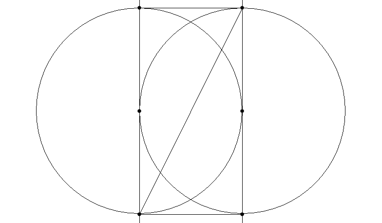
Or a rectangle with a diagonal which is √5:
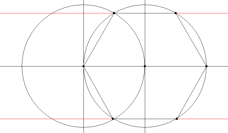
It can also be used to construct a hexagon:
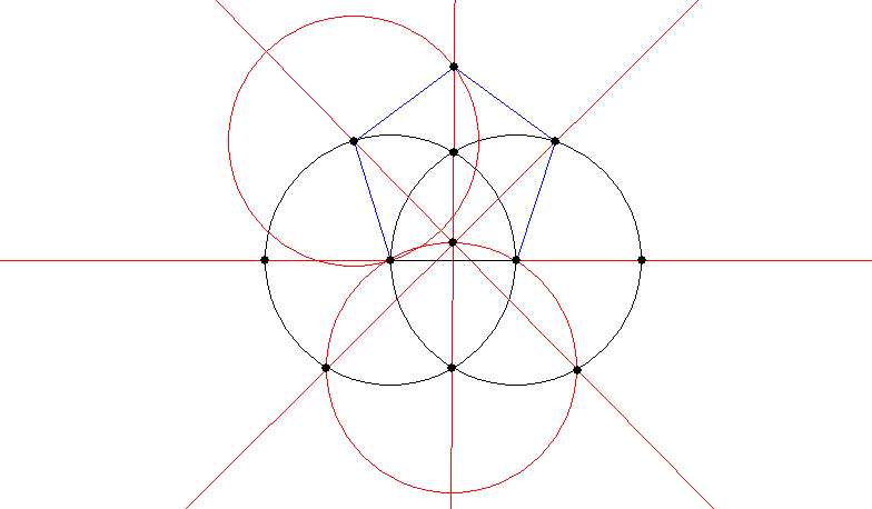
With the help of a couple more circles, you can construct a pentagon on it:
All of the above constructions are sourced from Robert Lawlor’s book Sacred Geometry (see below for bibliography).
The In-Triangle and Out-Triangle
An in-triangle is an equilateral triangle which fits exactly in a circle; an out-triangle is an equilateral triangle in which a circle exactly fits. The in-circle of a triangle is exactly half the size of its out-circle, usefully.
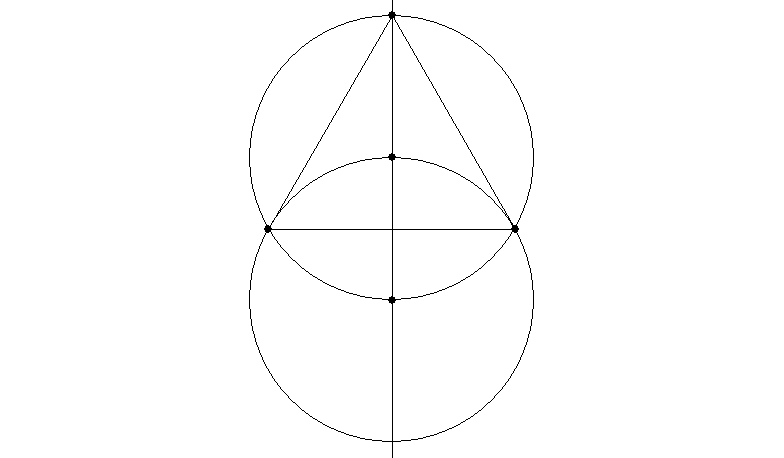
You can draw an in-triangle with the help of one additional circle:
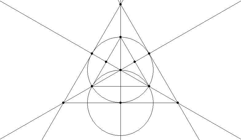
To draw an out-triangle is very easy with angled guidelines where you can set the number of degrees – just use guidelines at 120° from each other and make them tangents of the circle (that is, make them each contact the circle at just one point on its circumference). Here is a slightly more complicated way which requires you to work out the in-triangle and bisect two of its sides (see below for how to bisect a line segment):
The In-Square and Out-Square
The in-square and out-square work similarly to the in-triangle and out-triangle.
Probably the easiest way to draw an in-square is to put horizontal and vertical guidelines through the centre of the circle, connect the points at which they cut the circle, and rotate it 45° if required:
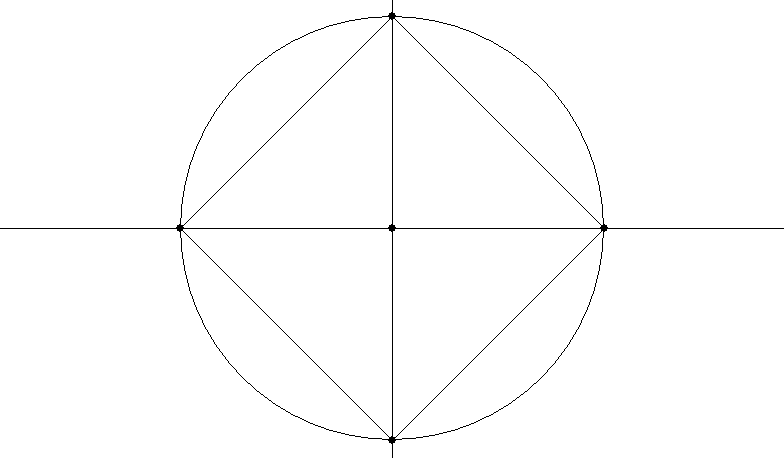
An out-square is also easy with horizontal and vertical guidelines which are tangent to the top, bottom and two sides of the circle.
The Pentagon
We have already looked at drawing a pentagon from a mandorla. Here are two ways to draw a pentagon inside an existing circle, the first from Lawlor (p. 36), the second from Lundy (pp. 26-27, see bibliography). In the Lawlor one, draw the lines and circle shown in red first, then the blue circle, then the green circles. In the Lundy one, draw the red, blue, green and brown circles in that order.
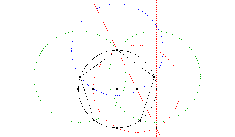
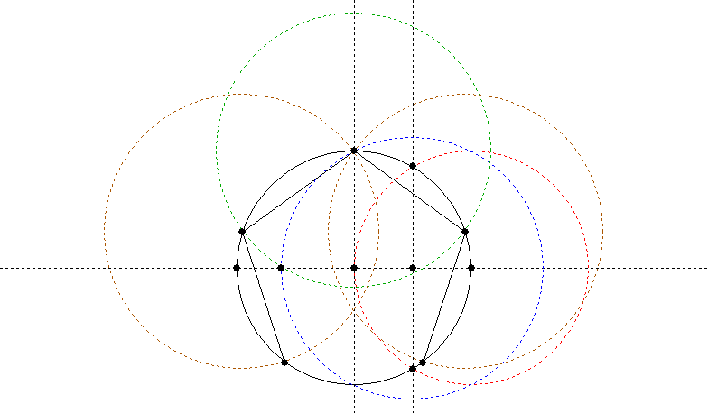
My books don’t tell me in detail how to draw an out-pentagon, so I have had to come up with my own (cheat’s) way, inspired by a diagram in Lawlor, p. 53. Draw an in-pentagon as above, then arrange guides which are tangent to your circle at the points where the in-pentagon touches it. (The guides will be at 72° intervals, since five of them make up the 360° of a circle.) You actually only need to place three (adjacent) guides, which will give you the length of one side by drawing a line between the crossing points of the guides. You can then duplicate and rotate that side five times, rotating 72° each time, and move the resulting lines until their end points touch and they form a pentagon.
Alternatively you could adapt the approach given above for the out-triangle (bisecting the sides, drawing a line through each vertex and the middle of the opposite side, and placing further lines which cross those at right angles where they meet the circumference of the circle).
Bisecting a Line Segment
We don’t need to look at drawing hexagons – we covered in-hexagons in the mandorla section, and you can apply the same approach to drawing out-hexagons as I gave above under pentagons. So let’s move on to a useful technique of bisecting a line segment, which I mentioned above under the triangle.
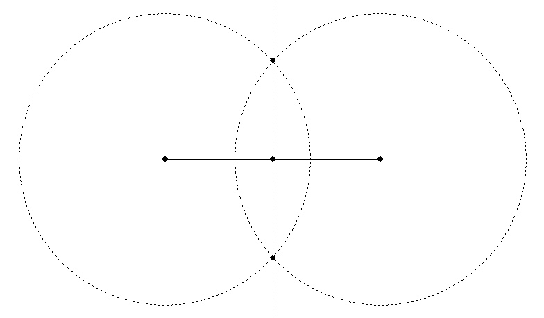
First, draw a circle of arbitrary radius (but with the radius more than half of the length of the line segment), centred on one end of the line segment.
Duplicate the circle and move the duplicate so that it is centred on the other end of the line segment.
The circles will cross at two points, and a line drawn (or a guideline created) between those two points will cross the original line segment at its exact centre:
Trisecting a Line Segment
Sometimes you want a third rather than a half. Here are a couple of different geometric ways to get a third.
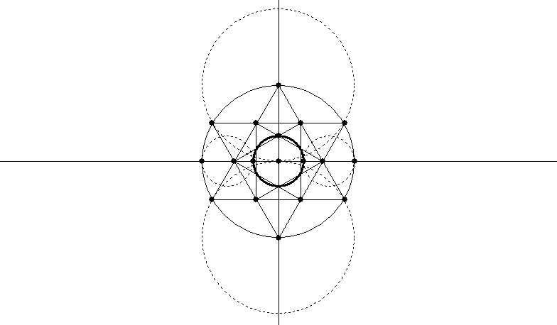
The first technique (Lundy, p. 20) is to draw a hexagram (Star of David) in a circle and another hexagram inside it. The circle constructed through the inner crossing points of the inner hexagram is one-third of the out-circle of the outer hexagram. (To draw the hexagram, create an in-triangle and invert a duplicate of it.)
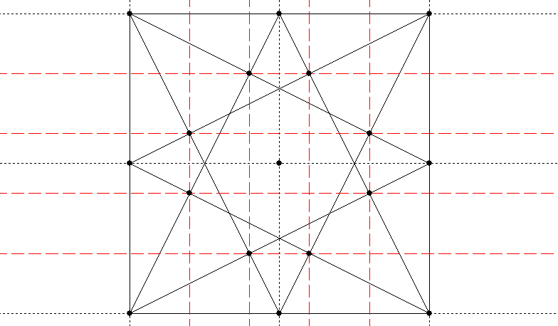
The other technique (Lundy, p. 32) involves dividing a square into nine squares. Use the bisecting technique or guidelines to get the centre of each side of the square, and draw lines from the centre of each side to the two corners of the opposite side:
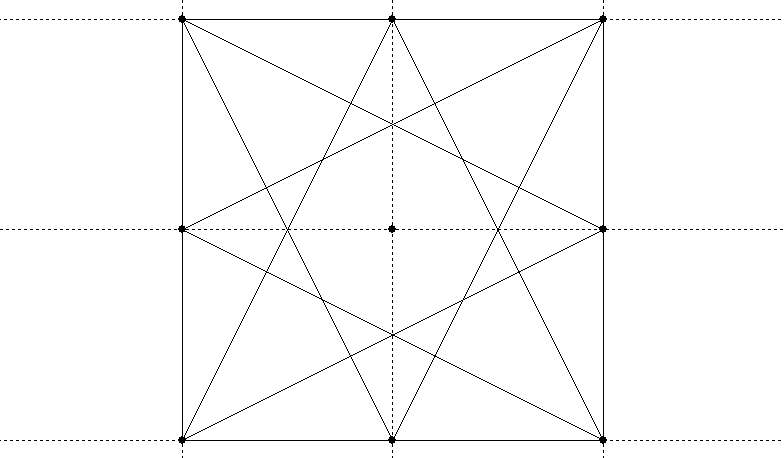
The four innermost crossing points divide the square into nine (and each side of it, therefore, into three):
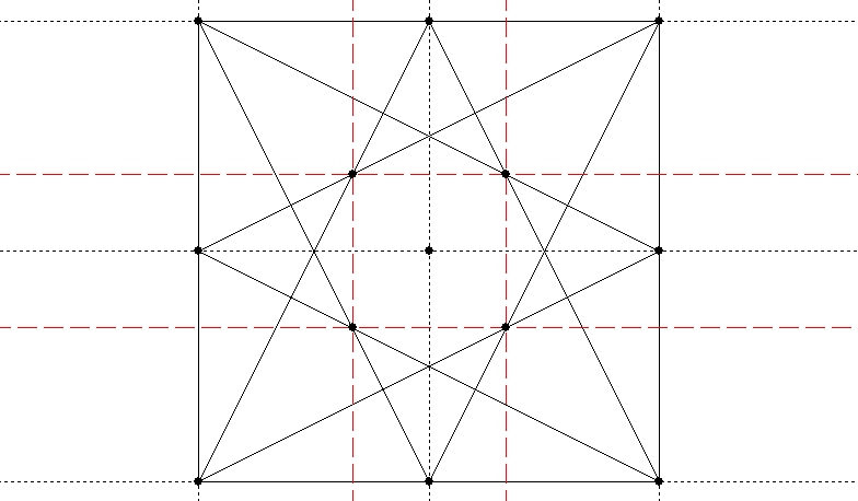
The middle four crossing points divide it into sixteen (and the sides into four):
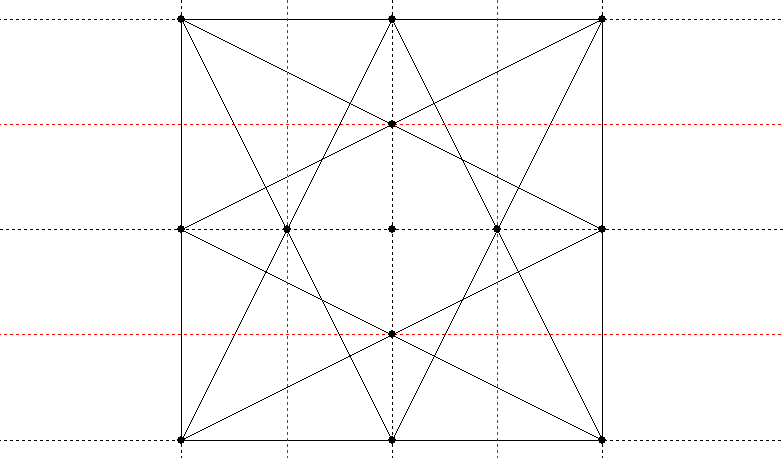
And the outer eight crossing points divide the square into twenty-five (and the sides into five, if you were wondering how to divide a line into fifths):
Packing Circles
The effect of packing circles into a geometric figure so that each one touches the next at only one point and they all touch the outside of the figure is a pleasing one. The simplest packing is six circles around a central circle, which you can do with circles of any size using this construction (Lundy, p. 9):
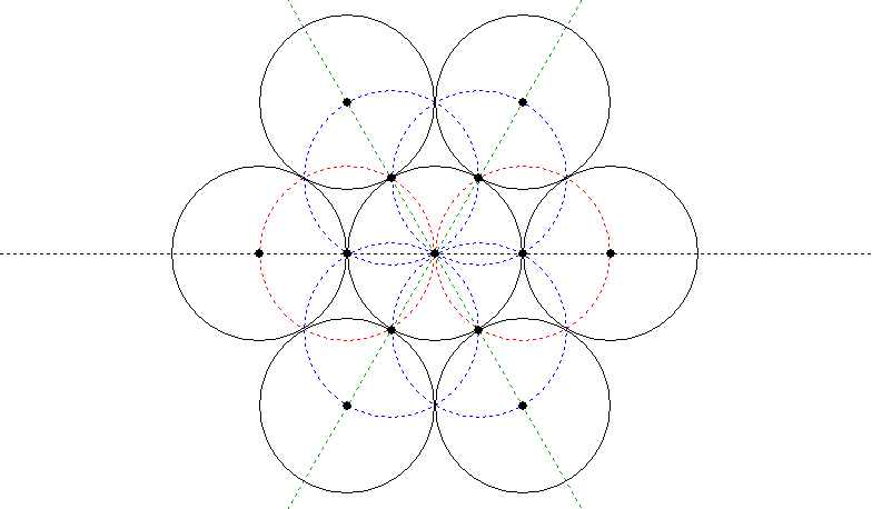
Draw the red circles first, then the blue circles, then the green lines to give you the centres for the outer circles.
If you wanted to pack the circles inside an existing circle, see the first technique under Trisecting a Line, above. You could use the same approach to pack them inside an existing hexagon by first drawing the hexagon’s in-circle.
Is there a general solution for packing circles inside an existing circle, though? Yes, there is. Lundy (p. 46), as is her way, gives several illustrations from which you can figure out the principle, without explaining it in her text.
Draw an out-polygon around the circle, with the same number of sides as you want circles. (A triangle for three circles, square for four and so on.)
Draw guidelines through the centre from the points (vertices) of the polygon and also from halfway along each of its sides (bisecting the sides as covered under Bisecting a Line, above).
The centres of the packed circles will be on one set of lines (either the ones from the vertices or the ones from the halfway marks), and the circumferences will be on the other set. Call them Set A and Set B.
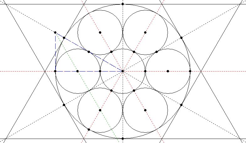
The tricky part is finding at what point on the lines the centres of the circles fall. To find this, you will need to construct a right-angled triangle, one side of which is formed by a vertical or horizontal line from either Set A or Set B, and the long side of which is formed by the immediately adjacent line from the other set.
You will then need to bisect the angle formed by the long side and the side which is at right angles to the vertical or horizontal line. The line constructed on this bisected angle cuts the vertical or horizontal line at the point where the circle’s centre should be placed.
I’m beginning to see why Miranda Lundy didn’t try to explain this – a diagram makes it much clearer. The red dotted lines are Set A and the black dotted lines Set B. The blue dashed lines outline the equilateral triangle, and the green dotted line is the bisector of the angle. Not shown is the construction circle you would probably draw from the figure’s centre through the first two centres you find (the ones on the green line), which would then give you the remaining centres.
To bisect an angle is one of Euclid’s early theorems. You can, of course, cheat and use your digital tools to measure the angle, then divide it by two (or if you’re using KSEG, it has a “bisect angle” button). But if you want a more classical method, here is my suggestion (I don’t have Euclid to hand right now, so I figured this one out from first principles).
First, make a sub-triangle which has sides of the same length on either side of the angle you want to bisect.
You can do this by drawing a circle of arbitrary size centred on the vertex where the angle to be bisected is, cutting both of the sides of the triangle which meet to form that angle.
Join the two points where the circle cuts the sides.
Now bisect the line you have just drawn using the method given under Bisecting a Line, above.
A line drawn from the vertex of the triangle through the midpoint of the opposite side will bisect the angle:
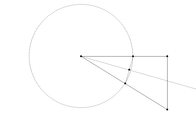
Note that the bisecting angle will not necessarily pass through the midpoint of the opposite side – this only occurs in special cases. So you can’t use that as a shortcut.
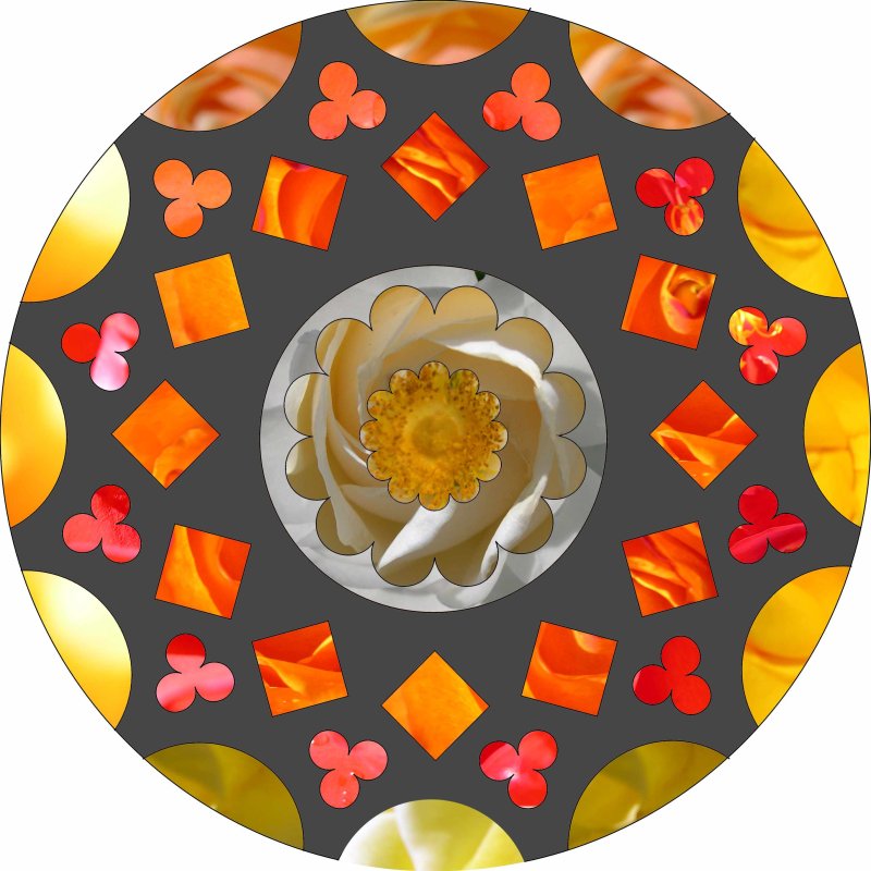
Once you have your packed circles, you can create pleasing lobed shapes by erasing the parts of the circles which fall inside the inner geometric figure (or using the Trim command in CorelDraw or its equivalent in other programs to remove the area where the objects overlap). See my article on Constructing a Digital Rose Window for an example – in that case the figure is a trefoil (three lobes), but you can use the same principle to create quatrefoils, cinquefoils and so forth.
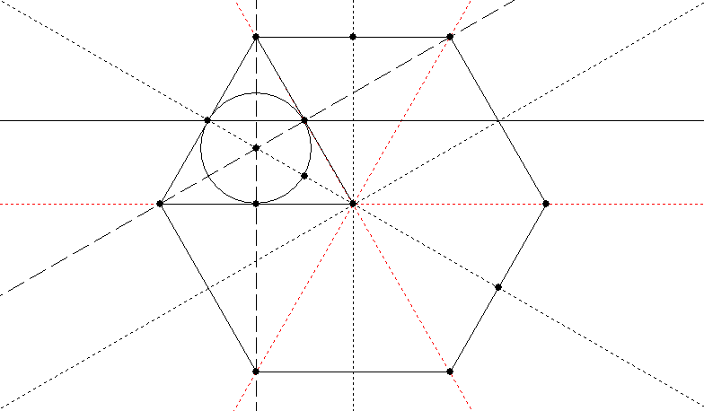
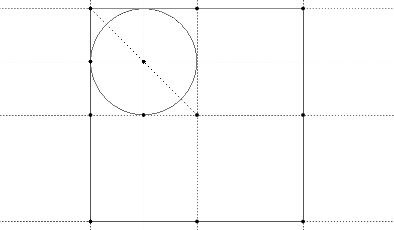
I wondered to myself: Is there a general method of packing circles in a given polygon, not just in a given circle? After playing around for quite a while I hadn’t found a general method (which isn’t to say there isn’t one), but I had found several specific methods for particular polygons. Basically you need to find a point which is equidistant from the outer boundary of the polygon and from the lines which pass through both its vertices and its centre, and which is not closer to the centre than it is to the boundary. Here is my first solution, for a hexagon, which being made up of equilateral triangles is easy:
My second, for a square (also easy):
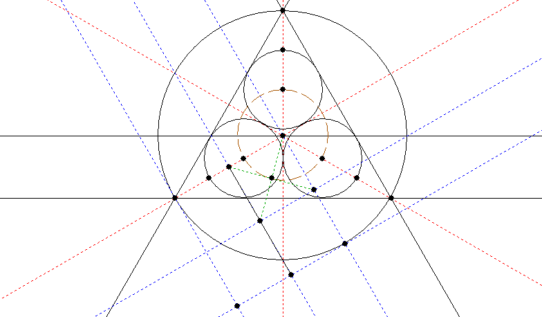
My third, for a triangle. This was a lot harder and involved several hours of experimentation. In the end I hit upon constructing a square on the diagonal from the centre to the lower left vertex (square shown in blue). The centre of the square (found by the green lines) is a point on the circle (brown) which, where it crosses the red guides, provides the centres of the packed circles. Whew!
I was going to leave the pentagon as an “exercise for the reader” – which is code for being too lazy to work it out – but I had got fascinated by this time and attempted the pentagon too. I worked these out, by the way, starting with the end state of a number of packed circles, drawing the polygon around them, and then trying to work backwards to find out how, given the polygon, I could have drawn the circles.
So my first task, having drawn circles around the vertices of a pentagon, was to draw the larger pentagon they all fitted into. I’ll record here how I did this (basically by constructing a square one circle-radius in width on several of the key points to give the larger pentagon):
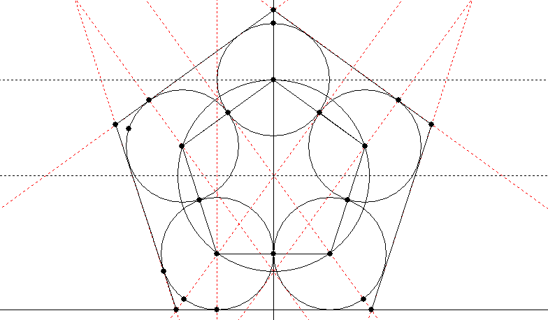
Now that I had my pentagon packed with circles, I could work backwards and attempt to find a construction which would give me the centres of the circles. Since a square helped me last time, I decided to go for the most obvious square (actually rectangle) – the one built on the pentagon’s baseline – and voila:
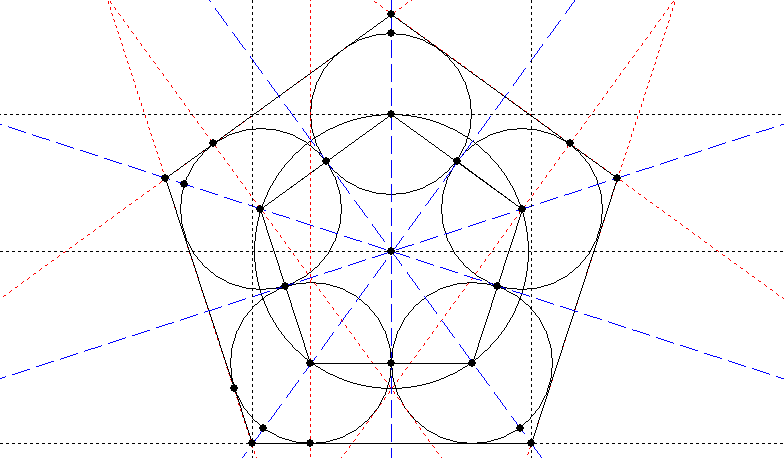
A circle the width of one of the pentagon’s sides, centred on the pentagon’s centre, gives the centres of the circles which pack that pentagon.
Sadly, this is not a general solution – it only appears to work for pentagons (as you will see if you try with the hexagon). If there is a general solution to the problem of fitting circles (equal to the number of sides) into a polygon, it has eluded me. Of course, I am completely ignorant of most of the work ever done in geometry, so the solution may well have been found centuries ago.
Drawing Significant Rectangles
There are several rectangles which are obviously well-proportioned to human eyes and which make a good basis for laying out your artworks. The first is the shape of the A series of paper sizes (A4 being the best known). This rectangle has the interesting property that when you cut it in half across the middle of the long sides, each half has the same proportions as the original. So an A5 sheet, for example, is half the area of an A4 sheet but has the same ratio of height to width (making the A series useful for reducing and enlarging photocopies).
The A series is a √2 rectangle (if you call the width 1, the height is √2 or approximately 1.414). It is easy to construct, because this is the proportion of the width of a square to its diagonal:
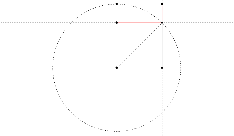
A circle with radius equal to the diagonal of your starting square gives you the √2 distance to construct your rectangle. The red portion is the area added to the original square to give the rectangle.
We already gave the mandorla construction of the √3 rectangle, but here is another way to do it (based on Mackinder, p. 14, see bibliography):
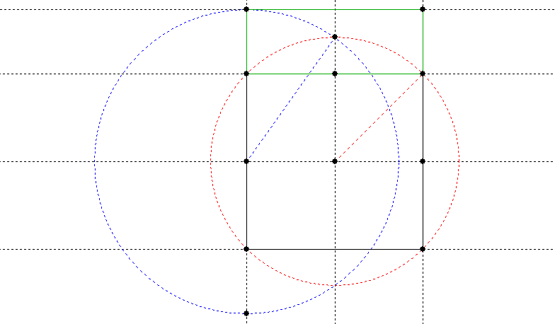
Start with a square divided into four. Draw the red circle first to give a √2 rectangle, then draw the blue circle which enlarges it to √3. The green portion is the area added to the original square to give the rectangle.
The so-called “golden rectangle” has the property that if you remove a square based on the shorter side, what remains is a golden rectangle. It is based on the distance from the middle of one side of a square to one of the opposite vertices (corners):
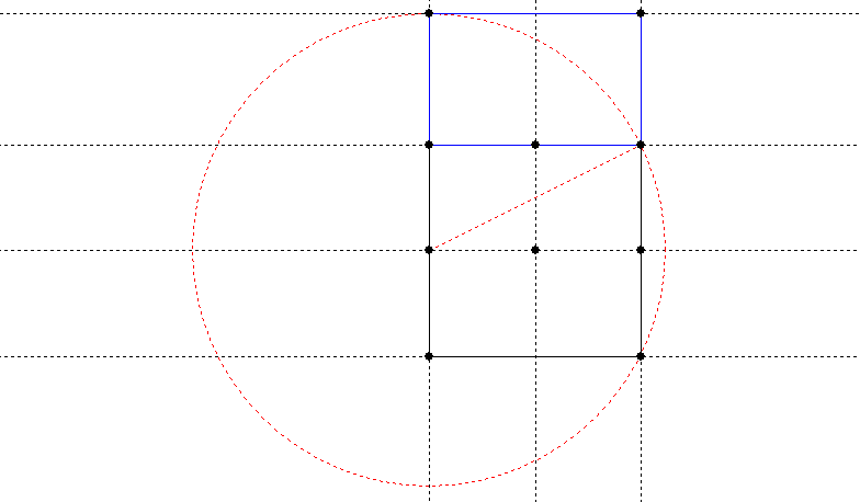
The blue portion is the area added to the original square to give the rectangle. This is a particularly easy construction.
The Golden Rectangle is supposed to be particularly aesthetically significant, besides being the sort of thing that someone like Lawlor gets very excited about because of its many unusual mathematical properties. It is based on the “golden proportion”, known by the Greek letter phi (φ). Its unique property is that the ratio 1: φ is the same as the ratio φ:1+ φ. It is approximately 1.618, and exactly (√5 + 1)/2.
Building Up a Layout
Once you have your base shape, whether square or rectangular, you can start drawing layout lines.
Start by getting the midpoints of each side (see Bisecting a Line, above). Draw vertical and horizontal guidelines which divide the rectangle or square into four equal parts.
If your layout is rectangular, construct squares based on the short sides (you can use a circle with its centre at one corner and its radius equal to the short side; where it cuts the long side is another corner of the square). Depending on the exact shape of the rectangle these will overlap or fall short of overlapping, giving you another rectangular space between them and two more points on the long sides.
Draw horizontals or verticals which divide the squares in half in whichever direction they are not already divided.
Join up all the points you now have on the outside of your rectangle, diagonally, in all the combinations you can think of. Join them to the centre as well.
The crossing points of these various diagonals (and the horizontal and vertical lines defining the halves of the squares and rectangles) will give you the basic points of your layout, from which you can proceed to draw concentric geometric forms, circles and what have you.
Two crossing points close together can be the basis for a measurement which can be used elsewhere in the piece, or to define the width of a border.
This is how the ancients did it, as you can prove by getting an accurate photograph of an ancient building or an artwork such as a page of the Book of Kells and drawing squares and diagonals. Many of the crossing points will be at significant points of the design (and most of the others are probably based on some more subtle geometry).
Conclusion
Those are the basics (as I see them) of digital sacred geometry. I haven’t covered spirals, fractals, sine curves etc.; maybe I will look at these later, when I have made some art with them.
For a worked example of creating a piece of digital sacred geometric art, have a look at my other article on Constructing a Digital Rose Window.
Bibliography
Lawlor, Robert Sacred Geometry (Illustrated Library of Sacred Imagination) (Thames and Hudson, 1982). Considerably more technical and theoretical than what I have presented here. Lawlor presents extensive material on both the “sacred” and “geometry” aspects, with illustrations from art, architecture and natural forms, as well as “workbooks” in which he presents the geometric and mathematical relationships between various figures.
Lundy, Miranda Sacred Geometry (Wooden Books, 1998). A much less technical and more practical book, small, but packed with useful constructions.
Mackinder, Jack Celtic Design and Ornament for Calligraphers (Thames and Hudson, 1999). As it was Jack’s night class which first turned me on to sacred geometry, I want to give his book a boost. It’s particularly strong on layout but covers all the basic aspects of Celtic design (knotwork, spirals, step patterns, key patterns, zoomorphics).
(All those links are Amazon affiliate links. If you buy, I get a tiny commission.)



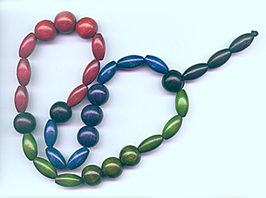 The 33 beads represent the years of Christ’s earthly life (as with the Anglican rosary), but they are grouped in threes and nines, traditionally sacred numbers